
Early Cyclone Detector
Arduino-Based Wind-Speed, Atmospheric-Pressure, Data-Logging and Emergency-Alert System
Disaster Management • Environmental Monitoring • Embedded Systems
The Early Cyclone Detector is an open-source educational and environmental-monitoring project. Its Arduino source code, circuit diagram, sensor connections, component links, technical documentation and project images are available through the Open Source Section.
Introduction
Cyclones and severe storms may be accompanied by rapid changes in wind speed and atmospheric pressure. Monitoring these environmental parameters helps in studying the conditions associated with developing storm systems.
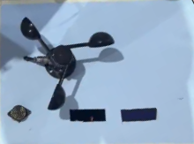
The Early Cyclone Detector was developed as an Arduino-based environmental-monitoring prototype. It combines a cup anemometer for observing wind speed with a BMP180 sensor for monitoring atmospheric pressure.
The project also integrates a DS3231 real-time clock for date and time, an SD-card module for storing observations, an I2C LCD for local information, a SIM900A GSM module for remote notification and a siren for immediate local warning.
Abstract
The Early Cyclone Detector is an embedded environmental-monitoring system designed to observe wind speed and atmospheric pressure. An Arduino Mega receives measurements from a cup anemometer and BMP180 sensor and processes them according to the programmed prototype warning conditions.
A DS3231 RTC module attaches date and time to every reading, while an SD-card module stores the collected information for later analysis. The I2C LCD displays live measurements and the current system status.
When an alert condition is detected, the Arduino can activate a relay-controlled siren and use the SIM900A module to send a GSM warning message.
Awards and Recognition
Theme-Wise Best Team Award
Recognition at the Science and Technology Hackathon of the India International Science Festival 2024 for the cyclone-pattern detection project.
View IISF Award CertificateDIGITEK Solutions Certificate
Research Excellence Certificate for the Early Cyclone Detector and its environmental-monitoring and cyclone-pattern detection work.
View DIGITEK CertificateFeatures
Scientific and Working Principle
The cup anemometer rotates when exposed to moving air. Faster air movement produces faster rotation. The sensor output is processed by the Arduino and converted into an estimated wind-speed value using the selected calibration.
The BMP180 measures atmospheric pressure. The Arduino continuously reads the wind and pressure information and compares it with the programmed prototype warning logic.
Every observation is assigned a date and time from the RTC module and stored on the SD card. The current wind speed, atmospheric pressure and system condition are displayed on the LCD. During an alert condition, the relay activates the siren and the GSM module sends a warning message.
Interactive Cyclone-Monitoring Simulation
Adjust the wind speed, atmospheric pressure and pressure fall. The virtual system updates the LCD, SD-card logger, indicator lights, siren and GSM status. The simulator is an educational demonstration and does not represent official cyclone-warning criteria.
Environmental Inputs
Sensor Dashboard
System Outputs
Real deployments require calibrated sensors, verified field data and official weather information.
Components Used
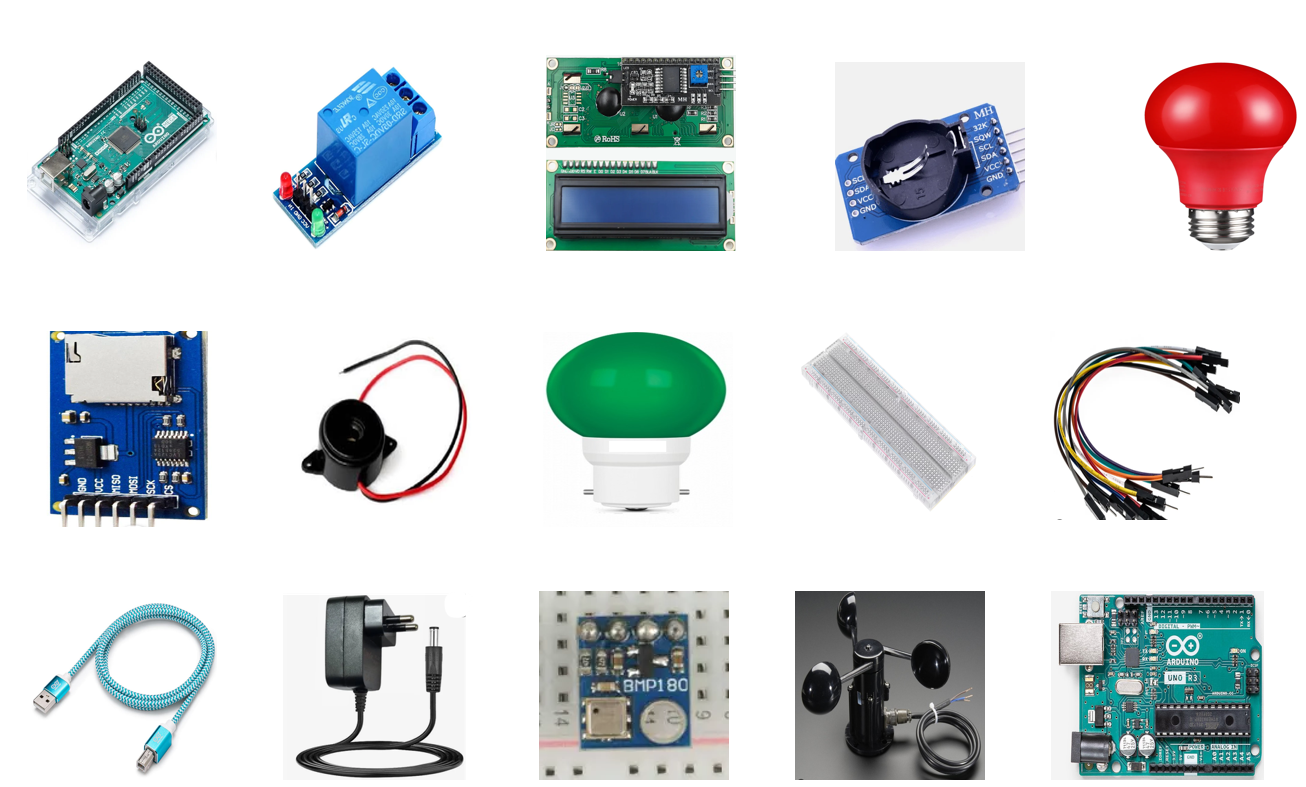
- Arduino Mega 2560
- Cup Anemometer
- BMP180 Atmospheric-Pressure Sensor
- DS3231 Real-Time Clock Module
- SD-Card Data-Logging Module
- 16×2 I2C LCD Display
- SIM900A GSM Module
- GSM Antenna
- Relay-Control Module
- Emergency Siren
- Normal and Warning Indicator Lights
- Active Buzzer
- Breadboard
- Jumper Wires and Connectors
- Regulated Power Adapter
- USB Programming Cable
Technical Description
The Arduino Mega 2560 serves as the main processing controller. It receives the anemometer output, reads atmospheric pressure from the BMP180, retrieves date and time from the RTC and updates the I2C LCD.
Environmental data are stored on the SD card in a structured format containing date, time, wind speed, atmospheric pressure and warning status. The saved observations can later be used for graphical analysis.
The SIM900A module provides remote communication. When the programmed warning condition is reached, the Arduino sends an SMS alert. A relay module controls the siren circuit.
| Component | Measurement or Function | System Role |
|---|---|---|
| Arduino Mega 2560 | Main microcontroller | Processes sensors and controls all system outputs |
| Cup Anemometer | Wind-speed observation | Provides calibrated wind-related sensor output |
| BMP180 | Atmospheric pressure | Measures changing pressure conditions |
| DS3231 RTC | Date and time | Time-stamps stored observations |
| SD-Card Module | Local storage | Records environmental readings |
| I2C LCD | Local display | Displays measurements and warning status |
| SIM900A | GSM communication | Sends remote warning messages |
| Relay and Siren | Local warning | Produces an audible emergency alert |
Methodology
- Study environmental parameters associated with cyclonic and severe-storm conditions.
- Select a cup anemometer for wind observation and the BMP180 for atmospheric-pressure monitoring.
- Integrate the sensors with the Arduino Mega and verify individual readings.
- Connect the DS3231 RTC and attach date and time to every observation.
- Store wind speed, atmospheric pressure and warning status on the SD card.
- Display real-time measurements on the I2C LCD.
- Develop prototype warning logic using combined wind-speed and pressure behaviour.
- Integrate the relay-controlled siren and SIM900A GSM alert system.
- Test the complete prototype using simulated environmental conditions.
Development Results
The prototype demonstrated wind-speed observation, atmospheric-pressure measurement, RTC date-and-time recording, local display and SD-card data logging.
The warning system demonstrated status indicators, relay-controlled siren operation and SIM900A communication under selected prototype test conditions.
Future Scope
- Calibrate the anemometer using a reference weather instrument.
- Add temperature, humidity and rainfall sensors.
- Transmit sensor data to an online dashboard.
- Analyse long-term SD-card observations graphically.
- Integrate official satellite and meteorological data.
- Apply machine-learning analysis after collecting a sufficiently large validated dataset.
- Add solar power and weather-resistant outdoor housing.
- Develop multi-location environmental sensor networks.
Open-Source Project Resources
Visit the Open Source Section for the Arduino source code, circuit diagram, anemometer connection, BMP180, RTC, SD-card, LCD, GSM and siren wiring, component links, technical documentation and project photographs.
Open-Source Educational Project
The Early Cyclone Detector is released as an open-source educational and environmental-monitoring project. Its source code, circuit diagrams, component information and supporting documentation may be studied, reused and modified according to the licence and attribution requirements published in the Open Source Section. Applicable attribution should be retained, and modified versions should be clearly identified.
Prototype Environmental-Monitoring System
The Early Cyclone Detector is an educational and experimental prototype. It must not replace official cyclone forecasts, warnings or evacuation instructions issued by authorised meteorological and disaster-management agencies. Real deployment requires calibrated sensors, validated thresholds, weatherproof construction and field testing.