
Reaction Time Tester
Arduino-Based Reflex and Coordination Assessment System
Embedded Systems • Human Performance • Interactive Electronics
The Reaction Time Tester is an open-source educational project. Its Arduino source code, circuit diagram, wiring information, component links, technical documentation and project photographs are available through the Open Source Section.
Introduction
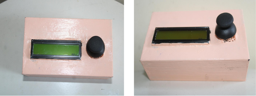
The Reaction Time Tester is an Arduino-based interactive device developed to measure how quickly a user responds to a randomly generated visual command. The device uses an Arduino Uno, an analog joystick and a 16×2 I2C LCD.
At the beginning of each trial, the user presses the joystick button to start the test. The system then waits for a random period so that the user cannot predict when the signal will appear. When the LCD displays START, the user must press the joystick button as quickly as possible.
The Arduino calculates the time between displaying the start signal and detecting the joystick response. The measured reaction time is displayed in milliseconds. Repeated trials can be used to observe reflex speed, response consistency and hand–eye coordination.
Objective
The objective of the project is to develop a simple, affordable and user-friendly electronic system that measures human reaction time in milliseconds through a randomized visual stimulus and joystick response.
The system is designed primarily for educational demonstrations, reflex-training activities and experimentation with response speed and coordination. It is not intended to replace professional medical or psychological assessment.
Abstract
The project uses an Arduino Uno as the main processing unit. A 16×2 I2C LCD displays instructions, the randomized start signal and the recorded response time. An analog joystick provides the user input through its integrated push button.
After the test begins, the microcontroller generates a random delay. If the user presses the joystick before the start signal, the system records a false start. Once the LCD displays START, the Arduino begins timing and stops when the joystick button is pressed. The result is shown in milliseconds.
Keywords: Reaction Time, Reflex Testing, Arduino Uno, Joystick, I2C LCD, Human Response, Coordination and Embedded Systems.
Features
Scientific and Working Principle
Human reaction time is the interval between the presentation of a stimulus and the initiation of a physical response. In this project, the visual word START displayed on the LCD acts as the stimulus, while pressing the joystick button acts as the response.
The Arduino records the starting time using its internal millisecond timer when the visual command appears. When the joystick button is pressed, the Arduino records the second time value. The reaction time is calculated by subtracting the stimulus time from the response time.
Interactive Reaction-Time Simulation
Press Start Test, wait for the LCD to display START, and then press the virtual joystick or the keyboard spacebar as quickly as possible. Pressing before START will be recorded as a false start.
Test Status
Reaction Statistics
Controls
Keyboard control: press Space or Enter to operate the virtual joystick. Do not press until the LCD displays START.
Components Used
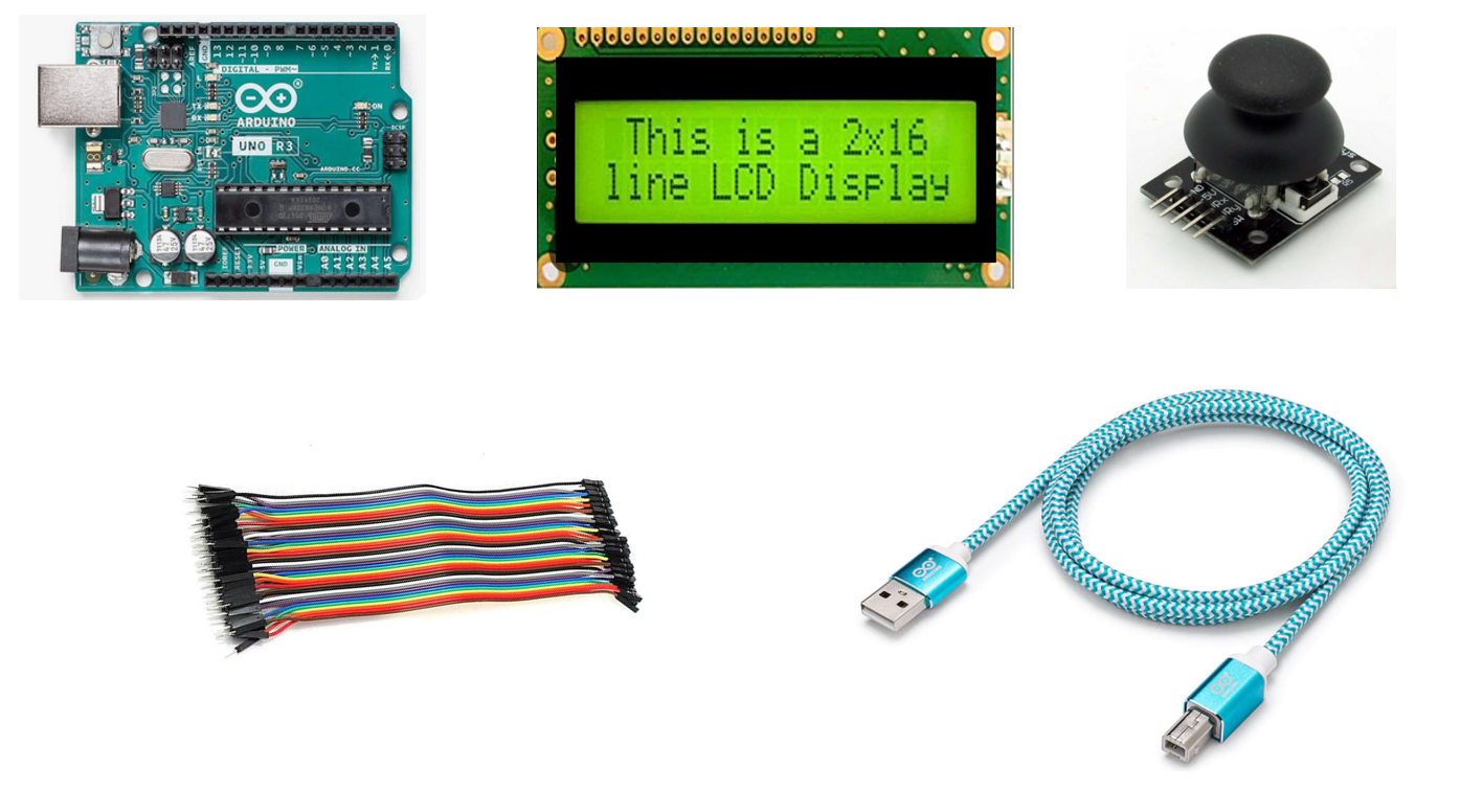
- Arduino Uno R3
- 16×2 Character LCD Display
- I2C LCD Interface Module
- Dual-Axis Analog Joystick Module
- Joystick Integrated Push Button
- Male-to-Male Jumper Wires
- USB Programming and Power Cable
- Prototype Enclosure
Technical Description
The Arduino Uno manages the complete operating sequence. The joystick push-button input is configured using an internal pull-up resistor so that a button press can be detected reliably. The LCD is connected through the I2C communication interface, reducing the number of required Arduino pins.
A random delay is generated at the beginning of every trial. During this period, the Arduino continuously checks whether the user has pressed the joystick early. After the random delay ends, START is displayed and the response timer begins.
| Part | Specification | Function |
|---|---|---|
| Microcontroller | Arduino Uno R3 | Controls timing, LCD output and joystick input |
| Display | 16×2 LCD with I2C interface | Shows instructions, START command and result |
| User Input | Analog joystick with push button | Starts the test and records the response |
| Timing Resolution | Millisecond-based Arduino timing | Calculates the reaction interval |
| Power | USB or regulated Arduino input | Powers the controller, joystick and LCD |
Circuit Design and Connections
I2C LCD Connections
The I2C interface allows the LCD to communicate with the Arduino through the SDA and SCL lines.
Joystick Connections
The joystick push-button line is used as the main response input. The X and Y axes may also be used in future versions for directional-response tests.
Methodology
- Study the concept of human reaction time and identify a suitable visual stimulus and response mechanism.
- Connect the Arduino Uno, I2C LCD and joystick module and verify individual component operation.
- Program the LCD to display instructions and test states.
- Generate a different random waiting period for every trial.
- Start the timer when the word START appears on the LCD.
- Stop the timer when the joystick button is pressed and calculate the response time.
- Display the measured result in milliseconds and identify false starts.
- Test repeated trials and refine button debouncing and timing reliability.
Applications
Experimental Results
The completed prototype successfully generates a randomized waiting interval, displays a START signal, detects the joystick response and presents the calculated reaction time on the LCD in milliseconds. The random delay prevents the user from predicting the start signal, while false-start detection identifies responses made before the command appears.
Future Scope
Open-Source Project Resources
For the complete project circuit diagram, Arduino source code, component-purchase links, wiring information, project photographs and technical documentation, visit the Open Source Section.
Conclusion
The Reaction Time Tester demonstrates how an Arduino, joystick and I2C LCD can be combined to create an interactive human-response measurement system. It provides immediate results, randomized timing and false-start detection in a compact and affordable form.
The project also offers a practical introduction to Arduino timing functions, digital input, random-number generation, LCD communication, button debouncing and interactive product development.
Open-Source Educational Project
The Reaction Time Tester is released as an open-source educational project. Its source code, circuit diagrams, component information and supporting documentation may be studied, reused and modified in accordance with the licence and attribution requirements provided in the Open Source Section. Applicable attribution should be retained, and modified versions should be clearly identified.